
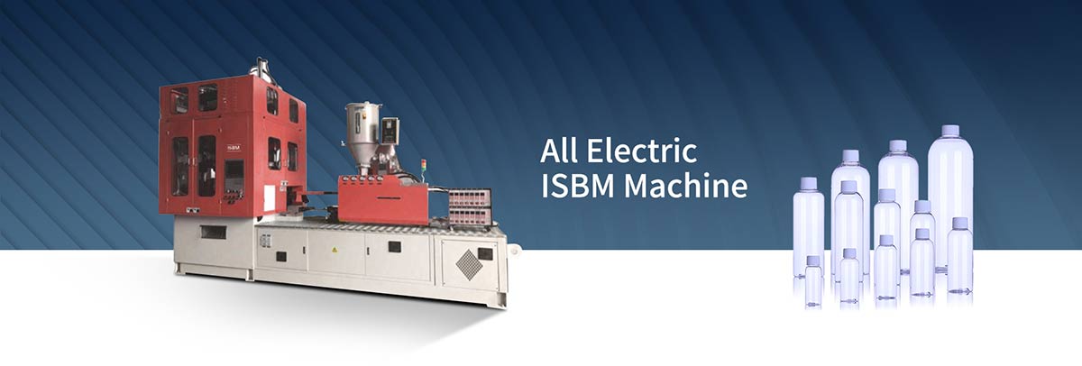
The injection blow molding process is an integrated manufacturing method used to produce hollow plastic containers with accurately molded necks, consistent dimensions and repeatable bottle geometry.
The process begins by plasticizing thermoplastic resin and injection molding it around a core rod to form a preform. The hot preform remains on the core rod as it is transferred into a blow mold. Compressed air then expands the preform until it conforms to the blow mold cavity. After sufficient cooling, the finished bottle is transferred to the ejection station and removed from the core.
A typical injection blow molding process can be summarized as:
Resin Feeding → Plasticizing → Shot Metering → Preform Injection → Packing → Thermal Conditioning → Core Transfer → Blow Molding → Cooling → Ejection
Although the basic sequence is relatively simple, stable production depends on precise interaction between material condition, melt preparation, injection molding, preform temperature, core rod condition, blowing pressure, cooling and tooling alignment.
Understanding these relationships is essential for controlling bottle weight, wall thickness, neck dimensions, surface quality and production consistency.
What Is the Injection Blow Molding Process?
The injection blow molding process, commonly called the IBM process, combines injection molding and blow molding within one integrated production cycle.
During the first stage, molten thermoplastic is injected into a mold around a metal core rod. This creates a preform with an accurately molded neck and a thicker body containing the material required for the finished bottle.
The injection mold then opens while the preform remains attached to the core rod.
The core rod transfers the hot preform into a blow mold, where compressed air expands the plastic outward until it reaches the cavity wall.
The bottle is then cooled sufficiently to retain its final shape before being transferred to an ejection station.
In a conventional three-station IBM system, the three principal operations are:
Injection → Blow Molding → Ejection
These operations can occur simultaneously on different sets of core rods, allowing continuous production.
Injection Blow Molding Process Flow
A complete IBM production cycle can be divided into the following stages:
- Resin feeding and preparation
- Plasticizing
- Shot metering
- Injection mold closing
- Preform injection
- Packing and holding
- Preform thermal conditioning
- Injection mold opening
- Core rod indexing
- Blow mold closing
- Blow air introduction
- Preform expansion
- Bottle formation
- Blow holding
- Cooling
- Blow mold opening
- Transfer to the ejection station
- Bottle ejection
- Bottle discharge and inspection
Each stage affects the next, which means a defect visible in the finished bottle may originate much earlier in the process.
Step 1: Resin Feeding and Material Preparation
The injection blow molding process begins with the thermoplastic resin.
Plastic pellets are supplied to the injection unit through a hopper. Depending on the polymer being processed, material preparation may include drying, blending, color dosing or additive mixing.
Consistent raw material condition is important because variations in resin properties can affect:
- melt viscosity;
- cavity filling;
- preform weight;
- surface appearance;
- wall thickness;
- bottle dimensions;
- processing stability.
Moisture-sensitive materials must be dried according to the requirements of the resin supplier.
Excess moisture can change processing behavior and, with some polymers, contribute to degradation or appearance problems.
Material contamination should also be prevented because foreign particles can affect the injection system, gates, preform surface and finished bottle quality.
For consistent production, resin type, resin grade, masterbatch ratio and material preparation conditions should remain controlled.
Step 2: Plasticizing the Resin
After entering the injection unit, plastic pellets are transported forward by the rotating screw.
Heat comes from both barrel heaters and mechanical shear generated during screw rotation.
As the resin moves through the barrel, it gradually changes from solid pellets into a homogeneous molten material suitable for injection.
The plasticizing stage must provide a melt with consistent:
- temperature;
- viscosity;
- mixing;
- shot volume;
- thermal history.
The objective is not simply to melt the polymer.
The melt must also be sufficiently uniform from one molding cycle to the next.
If plasticizing conditions fluctuate, preform filling and bottle quality can fluctuate even when other machine settings remain unchanged.
Melt Temperature
Melt temperature strongly influences injection behavior.
If the melt is too cold, flow resistance may increase and the preform cavities may become difficult to fill.
If the melt temperature is excessively high, the material may become difficult to control and may experience unnecessary thermal degradation depending on the resin.
The suitable melt temperature depends on factors such as:
- polymer type;
- resin grade;
- preform geometry;
- injection speed;
- mold temperature;
- cycle time.
A stable melt temperature provides the foundation for consistent preform production.
Screw Speed and Back Pressure
Screw speed influences how quickly material is plasticized.
Back pressure can affect melt mixing and consistency during screw recovery.
Excessive shear may generate unnecessary heat, while insufficient mixing may result in nonuniform melt conditions.
The correct combination should produce a homogeneous shot within the available cycle time without overheating or degrading the material.
Step 3: Shot Metering
Before each injection stroke, the screw prepares a controlled quantity of molten resin.
This measured amount is known as the shot.
Shot consistency is especially important in injection blow molding because the material contained in the preform becomes the material available for the finished bottle.
A simplified relationship is:
Preform Weight ≈ Finished Bottle Weight
If the injection shot changes, bottle weight is likely to change as well.
Variation in shot size can therefore lead to:
- inconsistent bottle weight;
- uneven wall thickness;
- cavity-to-cavity differences;
- inconsistent cooling;
- dimensional variation.
Stable metering is one of the basic requirements for repeatable IBM production.
Step 4: Injection Mold Closing
At the injection station, the injection mold closes around the core rods.
The core rod forms part of the internal geometry of the preform, while the injection mold defines its external geometry.
The mold must close accurately and provide sufficient clamping force to withstand injection pressure.
Correct alignment between the core rod and surrounding cavity is particularly important.
If the core is not centered correctly, the preform wall may become thicker on one side and thinner on the other.
This eccentricity can later appear as uneven wall thickness in the finished bottle.
Step 5: Preform Injection
Molten plastic is injected into the space between the core rod and the injection mold cavity.
This produces the preform.
The preform normally contains two distinct functional regions.
The first is the neck or finish region.
This may include:
- bottle opening;
- thread;
- sealing surface;
- flange;
- neck geometry.
These features are formed directly during injection molding.
The second region is the expandable preform body.
This thicker tubular section contains the plastic that will later expand into the body, shoulder and base of the finished bottle.
The quality of this preform has a major influence on the final container.
Step 6: Filling the Preform Cavity
During injection, molten resin flows through the runner and gate system and fills the space around the core.
Several variables influence this filling behavior:
- injection speed;
- injection pressure;
- melt temperature;
- mold temperature;
- gate geometry;
- runner balance;
- resin viscosity;
- cavity geometry.
A properly balanced injection stage should produce complete preforms with consistent weight and geometry across all cavities.
Poor filling may result in:
- short shots;
- uneven preform walls;
- flash;
- unstable weight;
- incomplete neck features;
- surface defects;
- cavity imbalance.
Because the preform is the starting point for the blowing stage, filling problems should be corrected before attempting to compensate for them with blow pressure or cooling adjustments.
Step 7: Packing and Holding
Once the cavity is substantially filled, holding pressure may remain applied for a controlled period.
This packing stage compensates for shrinkage as the molten polymer begins to cool.
Holding pressure and holding time can affect:
- preform weight;
- dimensional stability;
- neck accuracy;
- cavity balance;
- sink tendency;
- internal stress.
Insufficient packing may produce inconsistent preform weight or dimensional variation.
Excessive packing may increase stress, flash or unnecessary cycle time.
The goal is a stable and repeatable preform rather than maximum pressure.
Step 8: Preform Thermal Conditioning
After injection, the preform begins losing heat to the mold and core rod.
However, the expandable section must retain enough thermal energy to deform during the blowing stage.
This creates an important thermal balance.
The neck area requires sufficient stability to retain its molded dimensions.
The preform body must remain sufficiently soft and formable for expansion.
The process therefore depends on controlling heat transfer between:
- polymer;
- injection mold;
- core rod;
- ambient environment;
- blow tooling.
The temperature of the preform at the moment of blowing has a direct effect on material distribution.
Why Preform Temperature Distribution Matters
A preform can have the correct average temperature but still expand unevenly if temperature varies significantly from one region to another.
A hotter region generally deforms more easily.
A cooler region may resist expansion.
If one side of the preform is hotter than the other, material may preferentially move toward the hotter region during blowing.
This can result in:
- uneven wall thickness;
- asymmetric bottles;
- shoulder thickness variation;
- base thickness variation.
For consistent IBM processing, both overall temperature and temperature distribution are important.
Step 9: Injection Mold Opening
Once the neck and preform have reached the required condition, the injection mold opens.
The preform is not removed from the core.
Instead, it remains supported by the core rod.
This continuous connection between the preform and core is a fundamental characteristic of the injection blow molding process.
The core rod serves several functions:
- forms the inner surface of the preform;
- supports the preform;
- maintains neck alignment;
- transfers the preform;
- provides or supports the blow-air passage.
The preform therefore moves directly from injection molding to blow molding without being separately removed and reheated.
Step 10: Core Rod Indexing
The core rods carrying the hot preforms move from the injection station to the blow molding station.
In a conventional three-station rotary system, the indexing mechanism commonly rotates the core assembly from one station to the next.
During indexing, the preform continues to lose heat.
Transfer time therefore forms part of the thermal history of the process.
Consistent indexing helps maintain:
- repeatable transfer time;
- accurate mold alignment;
- stable preform temperature;
- reliable production timing.
Mechanical wear or inconsistent indexing can affect both positioning and process repeatability.
Step 11: Blow Mold Closing
At the blow molding station, the blow mold closes around the hot preform.
The blow mold defines the external geometry of the finished bottle.
Features formed by the blow cavity may include:
- shoulder profile;
- body diameter;
- body shape;
- bottle height;
- base geometry;
- external texture;
- decorative surface features.
Correct alignment between the preform, core rod and blow mold is essential.
If the preform is positioned off-center, one side may travel farther before contacting the mold wall, producing uneven wall distribution.
Step 12: Blow Air Introduction
Once the blow mold is fully closed, compressed air enters the preform through the blowing system.
Air pressure acts against the internal surface of the hot plastic.
The preform body expands outward until it contacts the cavity wall.
The transformation can be represented as:
Thick Preform → Radial Expansion → Thin-Walled Hollow Bottle
This is the primary bottle-forming stage of the injection blow molding process.
Step 13: Preform Expansion
Material distribution changes significantly during expansion.
The polymer initially contained in the relatively small preform must spread across the much larger surface of the finished bottle.
Different sections of the bottle can experience different levels of expansion.
For example:
- a wide body requires greater radial expansion;
- a narrow shoulder may require less expansion;
- a complex base geometry may redistribute material differently;
- sharp transitions can influence local wall thickness.
The final wall distribution is therefore determined by the relationship between the preform and bottle geometry.
Blow-Up Ratio
The dimensional relationship between the preform and the final bottle is an important factor in IBM design.
If the finished body diameter is significantly larger than the preform diameter, the material experiences greater radial expansion.
As the plastic spreads over a larger surface area, the wall becomes thinner.
The resulting wall thickness depends on several factors working together:
Preform Geometry + Preform Weight + Temperature + Expansion + Bottle Geometry
For this reason, wall thickness cannot be controlled effectively by changing only one machine parameter.
Step 14: Bottle Formation Against the Blow Mold
As the preform expands, its outer surface eventually contacts the blow mold cavity.
The plastic then begins replicating the external geometry of the mold.
This stage determines many visible features of the finished bottle.
Proper forming depends on sufficient:
- material temperature;
- blow pressure;
- airflow;
- mold venting;
- mold contact;
- cooling.
If the plastic does not completely contact the cavity, certain features may appear poorly defined.
Complex shoulders, corners and base features generally require particularly stable forming conditions.
Step 15: Blow Pressure and Blow Timing
Blow pressure provides the force required to expand the hot preform.
The appropriate pressure depends on factors such as:
- polymer;
- preform temperature;
- bottle size;
- bottle geometry;
- wall thickness;
- mold design.
Pressure alone, however, does not determine successful forming.
Blow timing is also important.
The relationship among:
Preform Temperature + Blow Pressure + Airflow + Time
determines how material moves during expansion.
A cooler preform may require different forming conditions from a warmer one.
Likewise, a large bottle body may behave differently from a compact container.
Stable production requires these variables to operate together within an appropriate process window.
Step 16: Blow Mold Venting
Before blowing begins, the cavity already contains air.
As the expanding plastic moves toward the mold wall, that air must escape.
Mold vents provide a path for displaced air.
Poor venting can trap air between the plastic and mold surface, resulting in:
- incomplete mold reproduction;
- poor surface definition;
- localized deformation;
- visible surface defects.
Vents must therefore remain clean and functional during production.
Step 17: Bottle Cooling
When the expanded plastic contacts the blow mold wall, heat begins transferring from the polymer into the mold.
Cooling stabilizes the bottle before removal.
The bottle must remain in the cavity long enough to achieve sufficient rigidity and dimensional stability.
Cooling influences:
- bottle shrinkage;
- dimensional accuracy;
- surface quality;
- post-mold deformation;
- cycle time.
If the bottle is removed while still excessively hot, it may deform after ejection.
If cooling time is unnecessarily long, production output decreases.
The objective is therefore sufficient cooling with stable heat removal.
Cooling Water Temperature and Flow
Blow molds typically use internal cooling channels.
Cooling performance depends on both water temperature and water flow.
A low coolant temperature alone does not guarantee effective cooling if circulation is restricted.
Potential cooling problems include:
- blocked channels;
- scale buildup;
- restricted hoses;
- low flow;
- uneven cavity cooling;
- unstable inlet temperature.
Uneven cooling can cause different cavities to produce different bottle dimensions or different regions of one bottle to shrink differently.
Cooling performance should therefore be evaluated as a complete heat-transfer system.
Step 18: Blow Holding
After the bottle reaches the mold surface, air pressure may be maintained for a period while cooling takes place.
This helps keep the plastic in contact with the cavity as its temperature decreases.
The required holding period depends on:
- material;
- bottle size;
- wall thickness;
- cooling efficiency;
- cavity geometry.
The bottle must become sufficiently stable before the mold opens.
Step 19: Blow Mold Opening
Once sufficient cooling has occurred, the blow mold opens.
The finished bottle remains associated with the core rod during transfer to the ejection station.
At this stage, the bottle has its final basic shape but may still contain residual heat.
It must have enough rigidity to survive:
- mold opening;
- indexing;
- ejection;
- downstream handling.
Insufficient cooling can result in bottle distortion during any of these steps.
Step 20: Transfer to the Ejection Station
The core assembly indexes again.
The finished bottles move from the blowing station to the ejection station.
At the same time, another set of preforms enters the blow mold and another set of core rods enters the injection station.
This simultaneous operation allows multiple stages of the IBM process to occur during the same machine cycle.
Step 21: Bottle Ejection
At the ejection station, the bottle is removed from the core rod.
The removal mechanism must release the container without damaging its molded features.
Special attention is required around:
- neck finish;
- opening;
- threads;
- shoulder;
- thin body walls.
The bottle may still be relatively warm, so excessive ejection force or poor handling can cause deformation.
Once removed, the core rods continue back toward the injection station to begin another cycle.
Step 22: Bottle Discharge and Inspection
Finished bottles leave the molding area and can proceed to downstream operations.
Depending on the production line, these may include:
- visual inspection;
- camera inspection;
- leak testing;
- weight inspection;
- dimensional inspection;
- counting;
- conveying;
- printing;
- labeling;
- packaging.
Quality inspection helps identify process drift before large quantities of nonconforming bottles are produced.
How a Three-Station IBM Cycle Works
A typical three-station injection blow molding system performs three operations at the same time.
While one group of core rods is producing new preforms, another group is blowing bottles and a third group is releasing previously molded containers.
The basic arrangement is:
| Station | Operation |
|---|---|
| Station 1 | Preform Injection |
| Station 2 | Blow Molding and Cooling |
| Station 3 | Bottle Ejection |
At the end of each cycle, the core assembly indexes.
A core group therefore follows the sequence:
Injection → Blow Molding → Ejection → Injection
Because all three stations operate simultaneously, overall cycle time is strongly influenced by whichever station requires the longest operating time.
What Determines Injection Blow Molding Cycle Time?
The injection blow molding cycle time is determined by the combined timing of several operations rather than one individual setting.
Important contributors include:
Plasticizing Time
The screw must recover and prepare enough melt for the next injection shot.
Injection Time
The preform cavities must be filled.
Packing Time
Pressure must be maintained long enough to produce stable preforms.
Preform Conditioning Time
The injected preform must achieve the required thermal condition.
Mold Opening and Closing
Mechanical mold movements consume part of the cycle.
Indexing Time
The core rods must move accurately between stations.
Blow Time
The preform must expand completely into the cavity.
Cooling Time
The bottle must achieve sufficient dimensional stability.
Ejection Time
Finished bottles must be removed before the next indexing movement.
Improving cycle time therefore requires identifying which operation is limiting overall production.
Critical Injection Blow Molding Process Parameters
The major IBM process parameters can be grouped into six categories.
1. Material Parameters
Material-related variables include:
- resin type;
- resin grade;
- melt-flow characteristics;
- moisture level;
- masterbatch ratio;
- additive concentration;
- material lot consistency.
Changes in material properties can alter filling, expansion and cooling behavior.
2. Plasticizing Parameters
Important plasticizing variables include:
- barrel temperature;
- screw speed;
- back pressure;
- recovery time;
- residence time;
- melt temperature.
Stable plasticizing provides a consistent starting condition for injection.
3. Injection Parameters
Important injection variables include:
- injection speed;
- injection pressure;
- shot size;
- transfer position;
- holding pressure;
- holding time;
- cushion;
- injection mold temperature.
These parameters primarily influence preform quality.
4. Thermal Parameters
Thermal control is particularly important in IBM.
Relevant variables include:
- melt temperature;
- preform temperature;
- core rod temperature;
- injection mold temperature;
- blow mold temperature;
- cooling-water temperature;
- cooling-water flow.
Consistent thermal balance improves repeatability during blowing.
5. Blowing Parameters
Important blowing variables include:
- blow pressure;
- air-flow capacity;
- blow start timing;
- blow duration;
- holding time;
- exhaust timing;
- mold venting.
These parameters influence how the preform expands and reproduces the mold cavity.
6. Mechanical Parameters
Mechanical condition also affects the IBM process.
Important factors include:
- core rod alignment;
- mold alignment;
- indexing accuracy;
- clamp condition;
- tooling wear;
- core wear;
- valve condition;
- ejector adjustment.
Mechanical variation can produce bottle defects even when process settings remain unchanged.
The Relationship Between Preform Quality and Bottle Quality
The preform contains all of the plastic that will eventually become the bottle.
The blow molding stage redistributes this material but does not add additional polymer.
This means preform quality has a direct influence on finished bottle quality.
Important preform characteristics include:
- weight;
- concentricity;
- wall thickness;
- temperature;
- neck dimensions;
- surface quality;
- cavity consistency.
An unstable preform can result in an unstable bottle.
For example:
Uneven Preform Wall → Uneven Expansion → Uneven Bottle Wall
or:
Inconsistent Preform Weight → Inconsistent Bottle Weight
or:
Uneven Preform Temperature → Uneven Stretching During Blowing
Controlling preform quality is therefore one of the most effective ways to improve overall IBM process stability.
Core Rod Temperature and Process Stability
The core rod directly contacts the internal surface of the preform.
Heat therefore transfers between the polymer and the metal core.
Core temperature influences how quickly the inner layer of the preform cools.
If different core rods operate at different temperatures, preforms produced in different cavities may behave differently during blowing.
Stable core conditions can help maintain:
- uniform preform temperature;
- consistent material expansion;
- cavity-to-cavity repeatability;
- stable bottle wall distribution.
Core rod cleanliness, wear and alignment should also be maintained because these affect both thermal behavior and geometry.
Injection Mold Temperature
The injection mold performs two important functions.
It forms the preform geometry and removes heat from the polymer.
The neck area requires enough cooling to retain accurate dimensions, while the expandable preform body must remain suitable for subsequent blowing.
Injection mold temperature therefore affects both preform stability and blowability.
The suitable thermal condition depends on:
- material;
- preform geometry;
- neck design;
- cycle time;
- core temperature;
- final bottle design.
Blow Mold Temperature
The blow mold defines the final external bottle shape and removes heat after expansion.
Blow mold temperature influences:
- cooling rate;
- bottle shrinkage;
- surface replication;
- dimensional stability;
- cycle time.
Uniform mold temperature is particularly important in multi-cavity production.
If one cavity removes heat faster than another, cavity-to-cavity dimensional differences can develop even when injection conditions remain stable.
Injection Blow Molding Wall Thickness Control
Bottle wall thickness is one of the most important quality characteristics in the IBM process.
Final wall distribution is affected by:
Preform Weight + Preform Geometry + Core Alignment + Temperature Distribution + Bottle Geometry + Blow Conditions
Wall thickness cannot therefore be controlled through a single adjustment.
Consider a bottle with a thin shoulder.
Possible causes may include:
- insufficient material in the corresponding preform region;
- locally high preform temperature;
- excessive local expansion;
- incorrect preform geometry;
- core misalignment;
- bottle geometry requiring excessive material movement.
Correct wall-thickness control begins by understanding where the material starts and how it moves during blowing.
Cavity-to-Cavity Process Control
Multi-cavity molds can produce acceptable average results while individual cavities behave differently.
For this reason, bottles should be evaluated according to cavity number whenever possible.
Useful cavity-specific measurements include:
- bottle weight;
- preform weight;
- bottle height;
- neck dimensions;
- wall thickness;
- surface appearance;
- base geometry;
- leakage performance.
If one cavity consistently produces a different result, the cause may be related to:
- runner balance;
- gate condition;
- core alignment;
- cooling;
- tooling wear;
- air distribution.
Cavity-based data makes root-cause analysis significantly easier.
Common Injection Blow Molding Defects and Causes
Understanding typical defects can help identify which part of the process requires adjustment.
Uneven Bottle Wall Thickness
Possible causes include:
- eccentric preform;
- core rod misalignment;
- uneven preform temperature;
- unsuitable preform geometry;
- asymmetric expansion;
- cavity misalignment.
The preform should be inspected before changing blow settings.
If wall imbalance already exists in the preform, the root cause is likely located in injection molding or tooling alignment.
Incomplete Bottle Formation
Symptoms may include poorly formed shoulders, corners or bases.
Possible causes include:
- preform temperature too low;
- insufficient blow pressure;
- inadequate airflow;
- restricted air passages;
- poor venting;
- unsuitable preform geometry;
- premature cooling.
Successful forming requires both adequate material deformability and sufficient air pressure.
Bottle Distortion After Ejection
Possible causes include:
- insufficient cooling;
- excessive bottle temperature at ejection;
- uneven mold cooling;
- thick local wall sections;
- inappropriate downstream handling.
A bottle may appear correct while inside the mold but deform after removal if it has not achieved sufficient thermal stability.
Preform or Neck Flash
Possible causes include:
- excessive injection pressure;
- excessive holding pressure;
- insufficient clamp force;
- mold wear;
- contamination on parting surfaces;
- mold misalignment.
Because the neck is created during the injection stage, neck flash is primarily associated with injection molding conditions or tooling condition.
Short Preforms
Possible causes include:
- insufficient shot size;
- low injection pressure;
- low melt temperature;
- restricted gate;
- poor venting;
- cavity imbalance;
- unsuitable material flow.
Short preforms should be corrected before the blowing stage is optimized.
Inconsistent Bottle Weight
Possible causes include:
- shot-size variation;
- material feeding instability;
- inconsistent cushion;
- non-return valve wear;
- unstable holding pressure;
- cavity imbalance.
Bottle weight is a useful diagnostic measurement because blowing redistributes material but does not normally change the amount of plastic in the bottle.
Poor Bottle Surface Quality
Possible causes include:
- resin contamination;
- inappropriate melt temperature;
- improper preform temperature;
- insufficient mold contact;
- trapped air;
- poor mold venting;
- blow mold surface condition;
- cooling imbalance.
The location and pattern of the surface defect can help identify its source.
Off-Center Wall Distribution
Possible causes include:
- core misalignment;
- eccentric preform;
- tooling wear;
- mold misalignment;
- uneven thermal conditions;
- asymmetric bottle geometry.
Measuring the preform before blowing can help determine whether the imbalance originates at the injection stage.
Injection Blow Molding Troubleshooting Procedure
A systematic troubleshooting approach reduces unnecessary parameter changes.
1. Check the Material
Confirm:
- correct resin;
- correct grade;
- correct drying condition;
- correct masterbatch ratio;
- absence of contamination.
2. Check Utilities
Verify:
- compressed air pressure;
- cooling-water temperature;
- cooling-water flow;
- electrical heating;
- air supply stability.
3. Check Mechanical Condition
Inspect:
- core rods;
- mold alignment;
- indexing;
- valves;
- clamps;
- ejectors;
- tooling condition.
4. Inspect the Preform
Measure or observe:
- weight;
- completeness;
- concentricity;
- neck geometry;
- surface condition;
- temperature;
- cavity-to-cavity variation.
5. Inspect Finished Bottles by Cavity
Separate production samples according to cavity whenever possible.
6. Identify Where the Defect Begins
Determine whether the abnormal condition already exists in the preform or appears only after blowing.
7. Change Process Variables Systematically
Adjust one meaningful parameter at a time and record the effect on bottle quality.
This method makes it easier to establish a clear relationship between cause and result.
Injection Blow Molding Process Control
Stable IBM production requires more than finding one set of machine settings that produces an acceptable bottle.
The process must remain repeatable over extended production.
Useful process-control data may include:
- cycle time;
- preform weight;
- bottle weight;
- melt temperature;
- cooling-water temperature;
- blow pressure;
- cavity number;
- dimensional measurements;
- defect rate.
Monitoring trends can reveal gradual changes caused by tooling wear, cooling deterioration, material variation or machine condition.
Process Window and Repeatability
A reliable IBM process should operate within a reasonable process window.
If acceptable bottles can only be produced at one extremely narrow combination of settings, the process may be sensitive to minor changes in material or environment.
A stable process should tolerate normal variation while maintaining required quality.
Process development should therefore focus on both:
Product Quality
and
Process Robustness
Repeatability is especially important in long production runs and multi-cavity molding.
Reducing Injection Blow Molding Cycle Time
Reducing cycle time can increase production output, but shortening individual timers without understanding the overall process can create quality problems.
Potential areas for cycle improvement include:
- plasticizing efficiency;
- injection filling;
- packing time;
- indexing;
- mold movements;
- blowing;
- cooling;
- ejection.
Cooling frequently represents an important part of the total cycle.
Improving cooling-water flow, channel condition or heat-transfer efficiency may allow production to increase without sacrificing bottle stability.
Likewise, optimizing screw recovery or mold movements may reduce nonproductive time.
The objective is to remove unnecessary time while maintaining preform quality, bottle geometry and repeatability.
IBM Process Documentation
A controlled manufacturing process should be documented so it can be reproduced across production shifts, mold changes and operators.
A typical IBM process record may include:
- resin type and grade;
- material drying conditions;
- barrel temperature profile;
- screw speed;
- back pressure;
- shot size;
- injection speed;
- injection pressure;
- holding pressure;
- holding time;
- cooling conditions;
- blow pressure;
- cycle time;
- bottle weight;
- key dimensions;
- cavity-specific inspection results.
Process documentation also makes troubleshooting easier because current conditions can be compared with a known stable baseline.
Injection Blow Molding Process vs Injection Stretch Blow Molding Process
Injection blow molding and injection stretch blow molding both use an injection-molded preform, but the bottle-forming stages are different.
In conventional injection blow molding, the hot preform is transferred into a blow mold and expanded primarily by compressed air.
The basic sequence is:
Injection → Transfer → Blowing → Cooling → Ejection
Injection stretch blow molding adds controlled axial stretching of the preform during bottle formation.
Its forming principle therefore includes both longitudinal stretching and radial blowing.
This difference influences material orientation, bottle properties and machine architecture.
Injection Blow Molding Process FAQ
What is the injection blow molding process?
The injection blow molding process is a method for manufacturing hollow plastic containers by injection molding a preform around a core rod, transferring the hot preform into a blow mold, expanding it with compressed air, cooling the bottle and ejecting the finished container.
What are the three main stages of injection blow molding?
The three main stages are:
Injection, Blow Molding and Ejection.
Additional operations include plasticizing, packing, thermal conditioning, indexing and cooling.
What does IBM process mean?
IBM stands for Injection Blow Molding. The IBM process combines injection molding of a preform with blow molding of the final hollow container.
How is the preform made?
Molten thermoplastic is injected between an injection mold cavity and a core rod. The mold forms the outside of the preform while the core forms the inside.
Why does the preform stay on the core rod?
The core supports the preform and transfers it from the injection station to the blowing station while maintaining its relationship with the molded neck.
How does the preform become a bottle?
Compressed air enters the hot preform and forces the plastic outward until it contacts the surface of the blow mold cavity.
What controls bottle wall thickness?
Wall thickness is influenced by preform weight, preform geometry, core alignment, temperature distribution, bottle geometry and blowing conditions.
Why is preform temperature important?
The preform must remain sufficiently warm to expand uniformly. Uneven temperature can cause uneven material distribution and inconsistent bottle wall thickness.
Why is cooling important?
Cooling stabilizes the bottle before removal from the mold. Insufficient cooling can result in shrinkage, distortion or dimensional variation after ejection.
What causes uneven wall thickness?
Possible causes include eccentric preforms, core misalignment, uneven temperature, unsuitable preform geometry and uneven material expansion.
What causes incomplete bottle formation?
Possible causes include low preform temperature, insufficient blow pressure, inadequate airflow, poor venting and unsuitable preform geometry.
How can IBM bottle weight be controlled?
Bottle weight is primarily controlled through stable material feeding, shot metering, injection filling and packing conditions.
What is the difference between IBM and ISBM?
Conventional IBM primarily uses compressed air to expand the preform. ISBM adds controlled axial stretching in combination with radial blowing.
How can the injection blow molding process be stabilized?
Stable production requires consistent material preparation, melt conditions, preform weight, preform temperature, core alignment, blow pressure, mold cooling and cavity-to-cavity control.
Conclusion
The injection blow molding process is a continuous manufacturing sequence in which every stage influences the quality of the stage that follows.
The complete process can be summarized as:
Material Preparation → Plasticizing → Preform Injection → Packing → Thermal Conditioning → Core Transfer → Blow Molding → Cooling → Ejection
Stable preform production provides the foundation for stable bottle production.
Consistent material preparation and plasticizing support repeatable injection molding.
Accurate core alignment and controlled injection conditions help produce uniform preforms.
Balanced preform temperature allows predictable expansion.
Correct blowing conditions distribute the material into the required bottle geometry.
Effective cooling stabilizes the bottle before ejection.
For this reason, injection, blowing and cooling should be treated as parts of one connected manufacturing process.
When material condition, preform quality, thermal balance, blowing conditions, cooling and tooling remain stable, the injection blow molding process can provide consistent bottle weight, accurate neck dimensions, controlled wall distribution and repeatable container quality.
Related Resources
Injection Blow Molding
Learn the principles of injection blow molding technology, including preform formation, core rods, bottle geometry and material distribution.
Injection Blow Molding Machine
Explore injection blow molding equipment for commercial plastic bottle production.
ISBM vs IBM
Compare injection stretch blow molding and injection blow molding technologies.
ISBM Process
Learn how the injection stretch blow molding process combines preform molding, axial stretching and radial blowing.