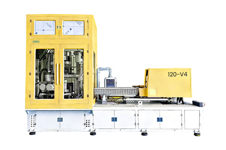
The 120-V4 provides a separate conditioning station between preform injection and stretch blowing. Its four-station layout and one-to-eight-cavity reference table make it a candidate for projects requiring both preform temperature conditioning and a defined bottle-to-cavity configuration.
Match the selected cavity layout, bottle geometry and conditioning tooling before confirming the machine configuration.
The 120-V4 separates injection, conditioning, stretch blowing and take-out. Its conditioning station lists a 250 mm core stroke and a 230 mm cavity stroke. This position forms part of the tooling and thermal-control proposal for the preform before blowing.
When assessing a bottle that needs a particular wall distribution, the proposal should describe how the selected preform and conditioning tooling address that requirement. The presence of a fourth station alone does not establish a shorter cycle or a better result for every bottle.
The 45 kW entry is the machine installed-power rating. Size the complete electrical supply using the actual material-preparation, cooling and air equipment included in the project.
Check the complete injection and tooling package. The 600 mm upper and 475 mm lower injection strokes, together with the 150 mm blow mold opening stroke, should be reviewed against the preform layout, neck tooling and mounting drawings.
Bottle configuration
Eight Cavity References, Each with Its Own Bottle Envelope
Read each row as a matched layout. Body diameter, neck size, height and weight from different rows must not be combined.
Swipe horizontally to view all columns.
Cavities
Body diametermm
Bottle heightmm
Neck sizemm
Bottle weightg
1
118
200
83
130
2
80
200
62
65
3
66
200
48
43
4
56
200
38
32
5
54
200
32
26
6
45
200
25
22
7
28
150
17
18
8
26
150
15
16
At one cavity, the reference pairs a 118 mm body with an 83 mm neck and a 200 mm height. At eight cavities, it pairs a 26 mm body with a 15 mm neck and a 150 mm height. Keeping each row together avoids combining a larger neck with an unsuitable cavity count. Final suitability depends on the bottle, preform and mold design.
Project planning
Plan Around the Four-Station Layout
Connect the conditioning arrangement, mold interfaces and installation requirements in one equipment proposal.
Review the Conditioning Tool and Mold Interfaces
Use the 250 mm conditioning core stroke and 230 mm conditioning cavity stroke, together with the mold dimensions and bottle geometry, to determine the proposed tooling arrangement.
For an existing or imported mold, provide mounting drawings, neck-handling details and the required station movements. The conditioning arrangement needs to match the actual tool; a general compatibility statement cannot replace this drawing review.
Allow for the Complete Production Cell
The 120-V4 machine dimensions are 4.3 × 1.4 × 3.1 m, with a listed weight of 5.5 t. Use the approved installation arrangement to plan the machine, mold access and selected auxiliary equipment.
The electrical schedule should include the machine's 45 kW installed rating and the material-preparation, cooling and air equipment specified for the project.
Length
4.3 m
Width
1.4 m
Height
3.1 m
Related model
Compare the 120-V4 with the 120-V3
The 120-V3 has different injection specifications and a three-station arrangement, despite sharing the 120 designation. Choose by bottle geometry, preform treatment and tooling fit.
If a taller bottle falls outside the 120-V4 reference envelope, include the 160-V4S in the engineering review.
Check the height limit for your cavity layout, existing-mold interfaces and the complete electrical requirement.
Are all eight cavity options suitable for a 200 mm bottle?
No. The catalog gives 200 mm for one through six cavities and 150 mm for seven and eight cavities. Other dimensions must also match the selected row.
Can an imported mold be used?
The catalog mentions mold compatibility, but the mounting drawing, neck handling, station movements and conditioning arrangement must be checked for the specific tool.
Is the 45 kW rating enough to size the complete production line?
It is the machine installed-power entry. The electrical schedule also needs the actual material-preparation, cooling and air equipment included in the project.
Discuss your bottle project
Request a 120-V4 Configuration
Supply a dimensioned bottle drawing, neck finish, target weight, resin grade and required output. For an existing mold, include mounting and interface drawings so the conditioning and tooling arrangement can be reviewed together.
Dimensioned bottle drawing and neck finish
Target bottle weight and resin grade
Required output and proposed cavity count
Wall-distribution or conditioning requirements
Existing mold mounting and interface drawings
Share a drawing link in the message, or send your files to info@isbmmachine.net.
Compatibility requires an engineering review of the actual tool and the selected bottle configuration.