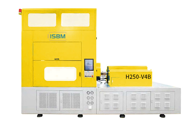
The H280S-V6 has a six-station configuration with two injection units described in its catalog. It requires a project review that defines the station sequence, tooling arrangement and material handling for the proposed PET or PETG container.
Build the proposal around a labeled process diagram, the role of each injection unit and the bottle acceptance requirements.
Stations, injection units and product quantities describe different aspects of the configuration. Confirm the active cavities and containers per cycle in the tooling proposal. Installed power is an electrical rating.
Model overview
Define the Six-Station Process in the Proposal
The H280S-V6 technical-standard section describes two injection units and two heater groups. This architecture calls for a station-by-station operating sequence linked to the proposed bottle, preform and tooling.
Request a labeled diagram showing what occurs at each station and how the two injection units divide the work. The supplied catalog does not define every station function or the allocation between the units.
Confirm those details in the approved configuration. Six stations do not establish six cavities, and two injection units alone do not establish two-color or multilayer production.
Identify all six process positions and show how the product moves through the machine.
B
Injection-Unit Allocation
Define the role, screw selection and shot requirement of each injection unit.
C
Tooling Arrangement
Specify the mold layout, active cavities and counting basis for the selected product row.
D
Bottle and Output Trial
Agree the resin, bottle-quality criteria and accepted-output target for the proposed sequence.
Technical data
H280S-V6 Machine Specifications
Keep the motor-power breakdown, heater groups and screw options explicit. The proposal should state the configuration of both injection units and whether each injection value applies to one unit.
Machine
Parameter
Specification
Drive
Hydraulic
Stations
6
Injection units
2
Specified materials
PET, PETG
Dimensions, L × W × H
5.9 × 2.6 × 3.2 m
Machine weight
14 t
Oil tank capacity
300 L
Electrical, Air and Cooling
Parameter
Specification
Main drive motor entry
29.8 kW
Injection-unit motor entry
75.4 kW
Total motor power
105.2 kW
Heater arrangement
10 + 10 kW
Total heating power
20 kW
Total installed power
125.2 kW
Blowing-air pressure
2.0 ~ 3.5 MPa
Cooling-water pressure
0.4 ~ 0.6 MPa
Oil-cooler water pressure
0.3 ~ 0.4 MPa
Oil-cooler water temperature
20 ~ 25 °C
Voltage
370 ~ 400 V
Injection Unit Options
Screw diameter
Theoretical injection volume
Screw rotation speed
40 mm
188 cm³
270 rpm
50 mm
350 cm³
220 rpm
55 mm
450 cm³
220 rpm
60 mm
600 cm³
220 rpm
Each row preserves one screw-option pairing. Confirm whether the volume and speed apply to one injection unit, and specify the allocation for both units. Do not double a published shot figure without that definition.
Station and Mold Movements
Parameter
Specification
Injection clamping force
150 kN
Injection upper stroke
250 mm
Injection lower stroke
205 mm
Conditioning core stroke
250 mm
Conditioning cavity stroke
230 mm
Blow clamping force, single side
200 kN
Blow core stroke
250 mm
Blow mold stroke
75 + 75 mm
Take-out stroke
170 mm
Define the shot for each injection unit. Specify the selected screw, resin grade, usable shot and assigned preform requirement. Theoretical injection volume in cm³ is separate from shot mass in g and requires its own application review.
Container configuration
Product References: 1 ~ 10 PCS
The catalog lists eight quantity entries: 1, 2, 4, 5, 6, 7, 9 and 10 PCS. Evaluate these product references independently of the six-station count.
Swipe horizontally to view all columns.
QuantityPCS
Body diametermm
Bottle heightmm
Neck sizemm
Weight referenceg
1
120
210
85
130
2
110
210
70
65
4
68
150
50
43
5
55
150
38
32
6
50
150
32
26
7
45
150
25
22
9
35
100
17
18
10
20
100
12
16
Read each row as one matched reference. Body, neck, height and weight limits from different rows must not be combined. Final suitability depends on the bottle, preform and mold design.
PCS retains the source quantity label and does not independently establish cavity count. Define the active cavities, containers per cycle and product movement in the approved mold and process drawings.
Drive and component configuration
Specify the Equipment Package for Both Units
Identify the actual servo-pump package, controls and actuation options in the quotation. Include how the selected equipment serves the two injection units and the approved station sequence.
Drive and Control Systems
Item
Catalog reference
Servo-pump package
Inovance with Sumitomo or WEICHI with OFITE
PLC
Inovance or MIRLE
Blow-clamp actuation
Hydraulic or dual-servo option
Plasticizing drive
Hydraulic or servo option
Valves and Temperature Control
Item
Catalog reference
High-pressure valve
Parker
Air cylinder
AirTAC
Hydraulic valve
YUKEN
Temperature control
Integrated control box or built-in system
The listed brands and alternatives describe the catalog reference. The quotation must identify the supplied package and any substitutions; every alternative is not included by default.
Tooling and installation
Connect the Process Diagram to the Machine Layout
Review the station sequence, tool movements and installation envelope together. Include access to both injection units when planning the production area.
Review the PET and PETG Reference Envelope
The one-PCS reference pairs a 120 mm body, 85 mm neck, 210 mm height and 130 g weight entry. At ten PCS, the table lists a 20 mm body, 12 mm neck, 100 mm height and 16 g weight.
Choose the relevant row using the complete container geometry and preform design. Confirm how the bottle and tooling move through the six positions, including the work allocated to each injection unit.
Check the 250 mm upper and 205 mm lower injection strokes, 250 mm conditioning core stroke, 230 mm conditioning cavity stroke and 170 mm take-out stroke against the final tooling drawing.
Plan Access to Both Injection Units
The listed machine envelope is 5.9 × 2.6 × 3.2 m, with a 14 t weight and a 300 L oil tank. Use the final equipment drawing to confirm installation space, mold access and service clearances.
The 29.8 kW main drive entry and 75.4 kW injection-unit motor entry total 105.2 kW. Two 10 kW heater groups add 20 kW, giving a total installed-power entry of 125.2 kW.
Use these entries for the machine electrical schedule and identify auxiliary equipment separately. Confirm the air, cooling-water and oil-cooler connections for the supplied configuration.
Length
5.9 m
Width
2.6 m
Height
3.2 m
Configuration comparison
Compare Against a Four-Station Proposal
Compare a four-station model only against the same container and production acceptance requirements. The H280S-V6 review centers on its six-position sequence and the allocation between two injection units.
Ask each proposal to explain how its tooling, injection configuration and product handling meet the required bottle specification and accepted output.
State each station function and the product movement
Injection configuration
Define each unit's role, screw option and usable shot
Production trial
Use the same bottle-quality and accepted-output criteria
Model questions
Questions About the H280S-V6
Confirm the process capability, tooling definition and proposal scope for the intended container.
Is this a two-color or multilayer machine?
The supplied catalog does not establish either capability. Two injection units alone are insufficient evidence for a two-color or multilayer production claim.
Is the station count the same as cavity count?
No. Stations describe process positions, while cavities and product quantity describe the tooling arrangement. They must be specified separately.
What should be included in an H280S-V6 proposal?
Include the six-station sequence, the role and configuration of each injection unit, the mold layout, the selected resin and an agreed bottle-quality and output trial.
Discuss your six-station project
Request an H280S-V6 Process Assessment
Provide the bottle drawing, resin grade, target mass, accepted output and any existing mold details. Request a proposal that defines the process sequence and both injection units.
Labeled six-station diagram and product movement
Role and configuration of each injection unit
Mold arrangement and active-cavity definition
PET or PETG grade and target container mass
Utility schedule and installation requirements
Agreed bottle-quality and accepted-output trial
Share a drawing link in the message, or send your files to info@isbmmachine.net.
Include existing mold and interface drawings where applicable so they can be reviewed against the proposed sequence.