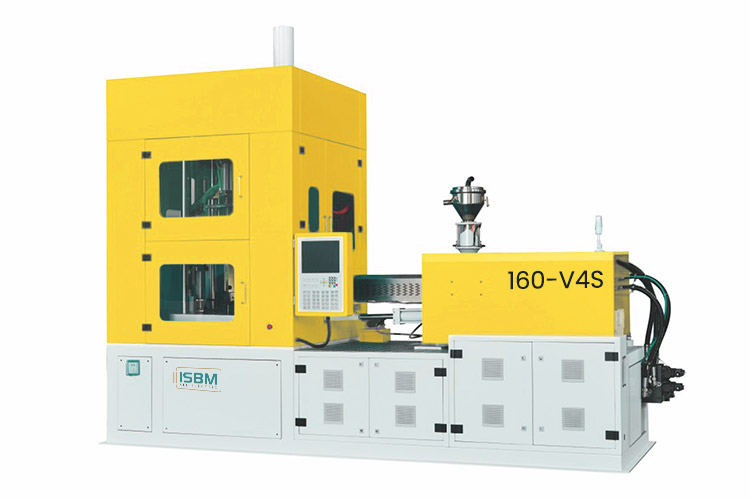
The 160-V4S combines a hybrid drive configuration with injection, conditioning, blow molding and ejection stations. Its reference table includes bottle heights up to 300 mm in the one-, two- and three-cavity rows, making height a useful starting point when assessing this model.
Review height together with the body diameter, neck finish and selected cavity layout for your container.
Seven- and eight-cavity configurations are special layouts requiring a bottle-specific tooling review.
Model overview
Assess Taller Bottles Within the Selected Cavity Layout
The 160-V4S provides separate injection, conditioning, blowing and ejection positions. Its product table gives a 300 mm height reference at one, two and three cavities, then changes the height allowance as the cavity count increases.
This makes it useful to compare a family of taller bottles at lower cavity counts with smaller formats on the same model. The cavity decision should follow the bottle dimensions and tooling study before a production target is assigned to the machine.
Form the preform with the selected screw and injection tool.
02
Conditioning
Condition the preform at a separate process position before blowing.
03
Stretch Blowing
Stretch and blow the preform into the selected bottle geometry.
04
Ejection
Remove the container through the configured ejection station.
Technical data
160-V4S Machine Specifications
Keep the screw and injection-volume entries paired. Review the electrical ratings, cooling circuits and air supplies as separate installation requirements.
Machine
Parameter
Specification
Drive
Hybrid
Stations
4
Oil tank capacity
450 L
Dimensions, L × W × H
4.5 × 1.95 × 3.0 m
Machine weight
5.5 t
Injection Unit
Parameter
Specification
Screw diameter
45 / 50 mm
Injection volume per shot
254 / 314 cm³
Screw L/D ratio
25, for the listed 50 mm screw
Theoretical injection mass, PET
380 g, for the 50 mm specification
45 mm screw: 254 cm³ per shot. 50 mm screw: 314 cm³ per shot. The separate 380 g PET entry is a mass specification, not an injection volume.
Clamping Specifications
Parameter
Specification
Injection clamping force
300 kN
Blow clamping force
120 kN
Power, Cooling and Air
Parameter
Catalog specification
Rated drive entries
24 / 11 / 7.8 kW at 380 V
Rated heater power
8.9 kW at 220 V
Cooling water flow
80 L/min
Cooling tower water flow
200 L/min
Maximum blowing-air pressure
4 MPa
Operating-air pressure
1.0 MPa
The drive entries are reproduced together as listed in the catalog. They are not presented as selectable alternatives or a total installed-power figure. Confirm the individual loads and final electrical schedule in the equipment proposal.
Specify one complete injection package. State the screw, resin, usable shot and operating conditions in the quotation. Keep the 45 mm and 50 mm volume entries paired with their respective screws, and identify the theoretical PET mass separately.
Bottle configuration
Distinguish Regular and Special Cavity Layouts
The catalog lists one through six cavities, plus seven- and eight-cavity entries marked as special. Read each row as a matched body, height and neck reference.
Swipe horizontally to view all columns.
Cavities
Body diametermm
Bottle heightmm
Neck sizemm
1
118
300
80
2
100
300
60
3
75
300
45
4
Review required†
200
35
5
55
200
30
6
44
200
20
7*
30
150
11
8*
25
100
10
* Seven- and eight-cavity layouts are special configurations requiring bottle-specific tooling evaluation; they are not assumed to be included in a standard quotation. † The four-cavity body-diameter entry requires clarification against the proposed mold layout before a project limit is confirmed.
At one cavity, the reference pairs a 118 mm body with an 80 mm neck and a 300 mm height. At three cavities, the corresponding body and neck references are 75 mm and 45 mm, also at 300 mm height. Bottle weight is not provided in this catalog table. Final suitability depends on the complete bottle, preform and mold design.
Project planning
Plan Cooling, Air and Mold Handling
Use the proposed bottle and mold layout to connect the hybrid four-station machine with the required utility supplies and factory space.
Keep the Cooling and Air Functions Separate
The catalog lists 80 L/min for cooling water and 200 L/min for the cooling-tower circuit. A plant layout should identify the connection points and supply conditions needed at the machine for each circuit.
Maximum blowing-air pressure is listed as 4 MPa, while operating-air pressure is 1.0 MPa. These entries describe different functions. Confirm the required air supply for the selected bottle process and equipment configuration.
Allow for Positioning and Mold Access
The 4.5 × 1.95 × 3.0 m equipment envelope and 5.5 t weight need to be considered when arranging access, positioning and mold handling.
For a family of bottle sizes, review each height, neck finish and body profile against its proposed cavity row. Define the mold layout and verified cycle conditions before assigning a production target.
Length
4.5 m
Width
1.95 m
Height
3.0 m
Related models
Compare the Actual Bottle Envelope
Review the 250-V4S when the body or neck dimensions require a different tooling envelope. Start with the matched bottle row, then compare the injection unit, clamping specifications and utilities.
The adjacent figures refer to one cavity on each model. They do not apply to higher cavity counts. For shorter containers, include the 120-V4 in the configuration review.
Clarify special cavity arrangements and the four-cavity body reference before finalizing the tool proposal.
Are seven and eight cavities standard arrangements?
They are marked as special cavity counts in the catalog. They require a bottle-specific tooling selection and should not be assumed to be included in a standard quotation.
Does the four-cavity row give one fixed body diameter?
It shows 58/66 mm. The meaning of those alternatives needs to be resolved with the mold layout before either value becomes a project limit.
What should be compared with the 250-V4S?
Compare the actual neck, body and height row first, then the injection unit, clamping specifications and utilities. The two models serve different tooling envelopes.
Discuss your bottle project
Request a 160-V4S Configuration
Provide the full-height drawing, neck finish, wall requirements, resin grade and target production rate. Request the proposed screw, mold layout and verified cycle conditions for your container.
Full-height bottle drawing and body profile
Neck finish and wall-distribution requirements
Resin grade and target production rate
Proposed cavity count, including any special layout
Available cooling, air and electrical supplies
Share a drawing link in the message, or send your files to info@isbmmachine.net.
The proposal should connect the selected screw and cavity layout with the complete bottle geometry and trial conditions.