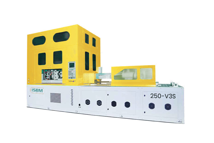
The 250-V3S is positioned for container projects requiring a three-station hybrid machine and a larger bottle envelope than the compact 50-series reference tables. Its process integrates injection, blowing and ejection without a separate fourth conditioning station.
Review the bottle and preform requirements together to select a cavity layout within this three-station platform.
An additional 10-cavity layout is marked as special and requires product-specific assessment. The 110 mm neck reference is listed for the one- and two-cavity layouts.
Model overview
Retain Three Stations with a Wider Container Envelope
The 250-V3S uses a hybrid three-station arrangement for injection, stretch blowing and ejection. Its one-cavity reference lists a 150 mm body, a 110 mm neck and a 300 mm height. At two cavities, the neck remains 110 mm while the body reference changes to 130 mm.
These pairings provide a practical basis for reviewing containers that need a substantial opening without automatically moving the project to a four-station machine. The selected bottle, preform and mold still need to fit the same cavity arrangement.
Form the preform with the 60 mm injection unit and the selected mold configuration.
02
Stretch Blowing
Stretch and blow the preform into the bottle body within the three-station process.
03
Ejection
Remove the molded container through the configured ejection arrangement.
Technical data
250-V3S Machine Specifications
Review the injection and clamp specifications as one package with the actual preform and tool, especially when more than one cavity is proposed.
Machine
Parameter
Specification
Drive
Hybrid
Stations
3
Oil tank capacity
610 L
Dimensions, L × W × H
4.8 × 2.0 × 3.0 m
Machine weight
11.5 t
Injection Unit
Parameter
Specification
Screw diameter
60 mm
Screw L/D ratio
24
Injection volume per shot
508 cm³
Theoretical injection mass, PET
640 g
Establish the usable shot and resin basis for the quoted machine configuration. Review both injection volume and theoretical PET mass against the proposed preforms.
Clamping Specifications
Parameter
Specification
Injection clamping force
780 kN
Blow clamping force
295 kN
Power, Cooling and Air
Parameter
Catalog specification
Rated drive power
37 kW at 380 V
Rated heater power
12.5 kW at 220 V
Cooling water flow
80 L/min
Cooling tower water flow
200 L/min
Maximum blowing-air pressure
4 MPa
Operating-air pressure
1.0 MPa
Confirm the electrical loads, cooling connections and air supplies in the installation schedule for the selected configuration.
Review the complete mold and shot requirement. The 60 mm screw, 508 cm³ injection volume and clamping specifications should be evaluated together with the actual preform, resin grade and proposed cavity count.
Bottle configuration
Review the Bottle Envelope by Cavity Count
The four-cavity row pairs a 100 mm body with a 70 mm neck and a 300 mm height. Select the complete row from the actual bottle and preform requirements.
Swipe horizontally to view all columns.
Cavities
Body diametermm
Bottle heightmm
Neck sizemm
1
150
300
110
2
130
300
110
3
130
300
90
4
100
300
70
5
80
250
42
6
66
250
35
7
55
200
30
8
48
200
24
10*
36
120
18
* The 10-cavity layout is a special arrangement requiring product-specific assessment. Its 36 mm body, 18 mm neck and 120 mm height references belong to that layout.
Read each row as one matched configuration. Body diameter, neck size and height from different rows must not be combined. Final suitability depends on the bottle, preform and mold design.
Project planning
Match the Three-Station Process to the Tool
Include the resin grade, neck drawing, container weight, target output and any existing mold details in the configuration request.
Review the Preform and Mold Together
The machine integrates injection, stretch blowing and ejection without a separate fourth conditioning position. Ask how the proposed process will prepare the preform for blowing and accommodate the selected mold.
When an existing tool is part of the project, submit its drawings and configuration details for review. Request trial criteria for bottle quality, cycle conditions and accepted output using the intended resin and cavity arrangement.
Use the 250-V3S Installation Envelope
The three-station machine is listed at 4.8 × 2.0 × 3.0 m and 11.5 t, with a 610 L oil tank. Use these model-specific figures when planning positioning, mold access and utility connections.
Keep cooling-water and cooling-tower connections identified separately. Confirm the required air supplies, electrical connections and auxiliary equipment in the final installation plan.
Length
4.8 m
Width
2.0 m
Height
3.0 m
Related model
Compare Three and Four Stations for the Same Bottle
The 250-V4S adds a separate conditioning position and has a different bottle envelope. Compare it when that process position is part of the proposed bottle solution, rather than assuming it is a direct replacement for the 250-V3S.
Ask how each proposed process will condition the preform and accommodate the mold. Use verified bottle quality, cycle conditions and tooling requirements to make the selection.
Check the model reference on older documents, the special ten-cavity layout and the basis for evaluating operating electricity use.
Why does an older table say JA-250-V3?
The catalog heading says JA-250-V3S while its product table says JA-250-V3. The current model mapping uses 250-V3S; the exact nameplate and drawing reference should accompany an order.
Is the ten-cavity configuration standard?
It is marked as a special arrangement. The catalog pairs it with a 36 mm body, an 18 mm neck and a 120 mm height reference.
Does the hybrid description guarantee lower electricity use?
It identifies a drive configuration. A comparison of operating electricity requires the same bottle, output definition, auxiliary scope and measured operating conditions.
Send your container specification
Request a 250-V3S Configuration
Include the resin grade, neck drawing, container weight, target output and any existing mold details. Request a configuration and trial criteria for the selected bottle before committing to production assumptions.
Complete body, height and neck-finish drawing
Resin grade, bottle weight and preform details
Required cavity count, including any special layout
Accepted-output target and bottle-quality criteria
Existing mold drawings and installation requirements
Share a drawing link in the message, or send your files to info@isbmmachine.net.
Identify the 250-V3S in your enquiry so the three-station configuration and its tooling requirements stay attached to the proposal.