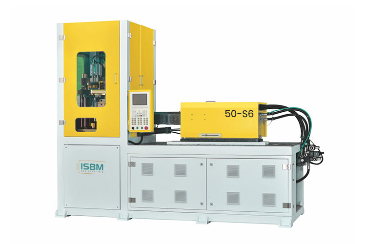
The 50-S6 is an all-electric three-station injection stretch blow molding machine. Its injection unit and rotary process support resin-to-container production within one machine.
Select it by matching the injection unit and cavity layout to your bottle, alongside the drive configuration.
The 36 mm screw, 146 cm³ theoretical injection volume and 100 cm³/s injection rate distinguish the 50-S6 from the 50-V5 specification. The catalog gives 210 MPa injection pressure and 25 kW installed power.
Its servo-controlled injection assembly provides a defined electric configuration to review. Specify the injection unit and mold together for the intended bottle and resin grade.
The servo-controlled injection assembly forms the preform.
02
Stretch Blowing
The rotary process transfers the preform for stretching and blowing.
03
Take-out
The container leaves the mold through the take-out station.
Technical data
50-S6 Machine Specifications
The all-electric drive, injection unit and station movements below describe the 50-S6 configuration. Keep these values together when preparing the equipment proposal.
Machine
Parameter
Specification
Drive
All-electric
Stations
3
Installed power
25 kW
Dimensions, L × W × H
3.4 × 1.2 × 2.5 m
Machine weight
3.5 t
Injection Unit
Parameter
Specification
Screw diameter
36 mm
Theoretical injection volume
146 cm³
Injection rate
100 cm³/s
Injection pressure
210 MPa
Screw rotation speed
0–200 rpm
Station and Mold Movements
Parameter
Specification
Injection clamping force
100 kN
Injection upper stroke
400 mm
Injection lower stroke
200 mm
Blow clamping force
70 kN
Blow core stroke
200 mm
Blow mold opening stroke
70 mm
Take-out stroke
100 mm
The 25 kW figure is the installed electrical rating. Energy per batch or per accepted bottle depends on measured operation under the agreed production conditions.
Keep the specified servo package traceable. Identify the selected injection motor, drive and controller in the equipment schedule so that the quotation, spare-parts information and delivered machine describe the same arrangement.
Bottle configuration
Select the Mold Layout from the Full Bottle Drawing
At three cavities, the reference pairs a 64 mm body with a 30 mm neck. At four cavities, it pairs a 45 mm body with a 27 mm neck. Use the complete row for each proposed bottle.
Swipe horizontally to view all columns.
Cavities
Body diametermm
Bottle heightmm
Neck sizemm
Bottle weightg
1
90
200
60
105
2
80
200
38
50
3
64
200
30
35
4
45
200
27
28
5
35
200
20
22
6
28
200
17
18
The catalog gives a common 200 mm height reference, but shoulder, base and neck geometry still require assessment. Check bottle weight, resin grade and the proposed mold for every format in a bottle family. A photographed six-cavity mold is an example configuration.
Project planning
Plan the Electric Configuration and Bottle Trial
Review the supplied controls, tooling interfaces and production-cell requirements before agreeing on the machine acceptance conditions.
Define the Servo and Installation Package
The 50-S6 combines a servo-controlled injection assembly with a three-station rotary process. Confirm the motor and controller package, mold configuration and included auxiliary equipment in the quotation.
The machine envelope is 3.4 × 1.2 × 2.5 m, with a listed weight of 3.5 t. Plan the installation around the selected tools and auxiliaries. Electric actuation still requires blowing air; specify pressure, flow and air treatment for the bottle process.
Length
3.4 m
Width
1.2 m
Height
2.5 m
Evaluate Operation with a Repeatable Trial
A useful acceptance trial records resin grade, bottle mass, active cavities, cycle time and approved quality checks. For the 50-S6, also identify the injection settings and servo configuration used.
If energy use is part of the purchase decision, define whether the meter covers the machine alone or the complete production cell. The 25 kW installed-power figure supports electrical planning; it does not establish a saving percentage or the energy required for one accepted bottle.
Related model
Compare the 50-S6 with the 50-V5
Review both proposals using the same bottle drawing, resin grade and output target. The 50-S6 has its own injection volume and stroke specification, which should remain attached to its selected mold and equipment package.
Review tool compatibility, compressed-air requirements and alternative electric configurations for your project.
Can a 50-V5 mold be moved directly to the 50-S6?
A similar bottle-size table is insufficient to establish interchangeability. The 50-S6 injection strokes are 400 mm upper and 200 mm lower, so the mounting and motion interfaces need checking.
Does all-electric mean that no compressed air is needed?
No. Electric actuation does not remove the blowing-air requirement. Air pressure, flow and treatment must be specified for the selected bottle process.
How does the H50-V3-EV compare?
It is a separate electric model with a 3.8 m machine length and different screw options. Use the same bottle drawing and output requirement when comparing it with the 50-S6.
Discuss your bottle project
Request a 50-S6 Configuration
Provide the bottle drawing, resin, neck specification and target output for a 50-S6 review. Define the measurement conditions and acceptance criteria if energy use, noise or repeatability is decisive.
Bottle drawings for each intended format
Resin grade, target mass and neck finish
Required output and bottle-quality checks
Existing mold drawings and interfaces
Power supply, available space and trial criteria
Share a drawing link in the message, or send your files to info@isbmmachine.net.
The final proposal should identify the servo configuration, mold layout and supporting equipment.