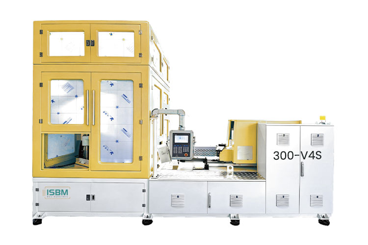
300-V4S Hybrid ISBM Machine for Multi-Cavity Production
The 300-V4S is a four-station hybrid machine with reference layouts from eight to twenty-four cavities. Its product table concentrates on smaller containers at higher cavity counts. The selection question is which layout fits the bottle and production requirement.
Match the bottle dimensions to a cavity layout, then establish the shot requirement and accepted-output target for that mold.
Nine reference layouts are listed: 8, 10, 12, 14, 16, 18, 20, 22 and 24 cavities. Each has its own matched bottle dimensions.
Model overview
Choose the Cavity Row Before Estimating Output
The eight-cavity reference allows a body up to 85 mm, a 50 mm neck and a 200 mm height. The twenty-four-cavity row lists a 25 mm body, a 13 mm neck and an 80 mm height. These rows describe different bottle projects and cannot be combined into a single maximum specification.
The 300-V4S starts its product table at eight cavities. Its selection range centers on multiple smaller containers, with neck, body and height references changing as the cavity count increases.
Supply the preforms for the selected multi-cavity mold in each cycle.
02
Conditioning
Condition the preforms at a separate station before stretch blowing.
03
Stretch Blowing
Form the bottle bodies within the selected cavity layout and process conditions.
04
Ejection
Remove the containers for the agreed inspection and downstream handling process.
Technical data
300-V4S Machine Specifications
Assess the injection requirement across all active cavities. Review the machine loads, cooling connections and air supplies for the proposed production setup.
Machine
Parameter
Specification
Drive
Hybrid
Stations
4
Oil tank capacity
630 L
Dimensions, L × W × H
5.5 × 2.12 × 3.13 m
Machine weight
15.5 t
Injection Unit
Parameter
Specification
Screw diameter
60 mm
Screw L/D ratio
24
Injection volume per shot
508 cm³
Theoretical injection mass, PET
640 g
Review the shot volume and theoretical PET mass against the resin grade, preform design and total shot required by the selected mold.
Clamping Specifications
Parameter
Specification
Injection clamping force
680 kN
Blow clamping force
280 kN
Power, Cooling and Air
Parameter
Catalog specification
Rated drive entries
31 / 31 / 15 kW at 380 V
Rated heater power
15.8 kW at 220 V
Cooling water flow
80 L/min
Cooling tower water flow
200 L/min
Maximum blowing-air pressure
4 MPa
Operating-air pressure
1.0 MPa
Confirm the individual motor loads, heater circuits and supply requirements in the electrical schedule for your configuration.
Plan for the machine and its handling equipment. The listed machine envelope is 5.5 × 2.12 × 3.13 m. Include tool access, container removal, conveying and auxiliary equipment in the installation layout.
Bottle configuration
Compare the 8 ~ 24 Cavity Layouts
Read each row as one matched reference. Higher cavity counts come with different bottle-size limits; dimensions from separate rows do not form a combined specification.
Swipe horizontally to view all columns.
Cavities
Body diametermm
Bottle heightmm
Neck sizemm
8
85
200
50
10
70
200
45
12
65
200
40
14
54
200
34
16
48
200
25
18
38
150
21
20
34
80
17
22
25
80
15
24
25
80
13
The 18-cavity row pairs a 38 mm body with a 21 mm neck and 150 mm height. At 20 cavities, those references change to 34 mm, 17 mm and 80 mm. Check all three dimensions when moving between layouts.
Final suitability depends on the complete bottle, preform and mold design. Confirm the resin grade and bottle mass with the selected cavity arrangement.
Production planning
Connect the Mold Layout with Accepted Output
Establish the required production rate using the proposed bottle and measured cycle conditions. A cavity count alone does not establish bottles per hour.
Connect Shot Demand with the Complete Mold
The injection specification includes a 60 mm screw, a 24 L/D ratio and a 508 cm³ volume entry, alongside a separate theoretical PET injection mass of 640 g. With multiple cavities, the proposal must account for the preforms supplied in each cycle and the specified bottle mass.
The number of cavities is only one part of the calculation. Resin preparation, filling behavior, conditioning and the cycle required for an accepted container should be evaluated together for the proposed tool.
Define Output Where Bottles Are Accepted
For a production comparison, report active cavities, measured cycle time and the proportion of bottles that meet the agreed specification. Calculate theoretical molding output as active cavities × 3,600 ÷ cycle time in seconds.
Accepted output also depends on yield and operating interruptions. Define the measurement period and acceptance criteria, then check conveying and packing capacity against the resulting production target.
Active cavities
Count
Measured cycle
Seconds
Accepted output
Bottles/h
Related models
Compare the Relevant Alternatives
The 250-V4S addresses a different container envelope, while the H250-V4B offers a separately documented double-row layout. Compare them using the same bottle drawing, resin grade, bottle weight and acceptance requirements.
The H250-V4B product quantities are labeled in PCS; the 300-V4S table labels cavities. Confirm what each quantity represents in the proposed mold and cycle before comparing output.
Nine cavity references for smaller-container, multi-cavity production.
250-V4S
A different container envelope for larger bodies and wider necks.
H250-V4B
A separately documented double-row arrangement with quantities labeled in PCS.
Model questions
Questions About the 300-V4S
Check the 24-cavity bottle limits, how production rate is established and the basis for comparing alternative layouts.
Can the 24-cavity layout produce the largest listed container?
No. Its reference is a 25 mm body, a 13 mm neck and an 80 mm height. The larger eight-cavity envelope is a separate arrangement.
Does the model number represent a guaranteed production rate?
No. Output must be established from the selected mold and measured cycle. The model designation is not a bottles-per-hour specification.
How is this different from H250-V4B?
H250-V4B explicitly documents a double-row arrangement and labels its product quantities in PCS. The 300-V4S table labels cavities. Those terms should be reconciled before comparing output.
Discuss your production project
Request a 300-V4S Configuration
Send a bottle drawing, resin grade, bottle weight and output target for a 300-V4S proposal. Include the proposed cavity count and downstream handling requirements so the molding and packing stages can be assessed together.
Body diameter, height and neck-finish drawing
Resin grade, bottle weight and preform details
Proposed cavity count and production target
Acceptance criteria and production measurement period
Container removal, conveying and packing requirements
Share a drawing link in the message, or send your files to info@isbmmachine.net.
Request the cavity arrangement, cycle conditions and utility requirements for the selected bottle.