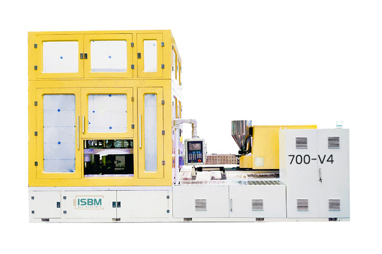
The 700-V4 has separate injection, conditioning, blowing and take-out stations. Its bottle reference table lists a 350 mm height across the available cavity entries, with neck and body limits that change by mold layout.
Review the neck geometry, bottle dimensions and matched screw option together before selecting the tooling configuration.
The 350 mm height reference is listed across all eleven cavity layouts. Neck, body and bottle-weight references must be taken from the selected row.
Model overview
Review Large-Neck and Tall-Container Requirements
The one-cavity reference pairs a 204 mm body with a 149 mm neck. At four cavities, the reference is a 120 mm body and a 95 mm neck. Both list a 350 mm height, but each represents a different mold layout.
At twelve cavities, the body and neck references reduce to 37 mm and 18 mm. The full table supports an initial assessment of tall-container projects without implying that all widths, necks and cavity counts can be combined.
Confirm the final electrical supply, connected loads and auxiliary requirements in the installation proposal.
Station and Mold Movements
Parameter
Specification
Injection clamping force
700 kN
Injection upper stroke
450 mm
Injection lower stroke
325 mm
Conditioning core stroke
275 mm
Conditioning cavity stroke
250 mm
Blow clamping force
265 kN
Blow core stroke
275 mm
Blow mold opening stroke
300 mm
Take-out stroke
150 mm
Assess all four stations for the selected container. Injection, conditioning, blowing and take-out movements serve different parts of the tooling sequence. Check each movement alongside the bottle and preform drawings, including neck handling and removal.
Injection configuration
Choose a Complete Screw Option
Selecting a larger screw changes injection volume, rate and pressure together. Keep the values in each column attached to the same proposed configuration.
Swipe horizontally to compare all screw options.
Parameter
45 mm screw
50 mm screw
60 mm screw
Theoretical injection volumecm³
389
481
692
Injection ratecm³/s
190
240
340
Injection pressureMPa
217
176
122
Screw rotation speedrpm
0 ~ 150
The 692 cm³ volume belongs to the 60 mm screw and cannot be paired with the 217 MPa pressure entry from the 45 mm column. Specify one complete injection option in the quotation.
Bottle configuration
A 350 mm Height Reference Across the Listed Layouts
Body diameter, neck size and bottle-weight references change with cavity count. Read each row as one matched layout and verify it against the proposed bottle.
Swipe horizontally to view all columns.
Cavities
Body diametermm
Bottle heightmm
Neck sizemm
Weight referenceg
1
204
350
149
311
2
153
350
120
156
3
130
350
99
104
4
120
350
95
78
5
99
350
73
62
6
79
350
57
52
7
66
350
42
44
8
54
350
36
39
9
53
350
34
35
10
45
350
27
31
12
37
350
18
26
Dimensions and weight references from different rows must not be combined. The 149 mm neck reference applies to one cavity; the twelve-cavity row has an 18 mm neck reference.
Final suitability depends on the bottle, preform and mold design. Include the resin grade and target bottle mass in the project review.
Project planning
Compare the Tooling and Installation Proposal
Provide the bottle drawing, resin grade, target mass, output requirement and existing mold interfaces so the proposed configuration can be reviewed as a complete system.
Check Neck Handling and Station Clearances
The injection upper and lower strokes are 450 and 325 mm. Conditioning uses a 275 mm core stroke and a 250 mm cavity stroke; the blow station lists a 275 mm core stroke and a 300 mm opening stroke.
Check these movements with the preform length, neck-handling arrangement and mold drawings. Include the 150 mm take-out stroke when reviewing how the finished container will be removed.
Plan for the Machine and Auxiliary Equipment
The listed machine envelope is 5.4 × 2.15 × 3.3 m, with a weight of 13 t. Confirm auxiliary equipment and service clearance on the installation drawing.
Keep the selected screw configuration, mold interfaces and final utility schedule attached to the same proposal. Establish the installation layout around the equipment to be supplied.
Length
5.4 m
Width
2.15 m
Height
3.3 m
Related model
Compare 700-V4 and 250-V4S Using One Bottle Drawing
The 250-V4S is relevant for some larger-neck projects, but its hybrid drive, injection specification and height references differ. Compare both models using the same container, preform and mold requirements.
For the 700-V4, identify which of the three screw options is being proposed. The comparison below uses its 60 mm option only for the injection-volume row.
Review screw-option relationships, the information required for bottle selection and the basis for comparing related models.
Does the largest screw also have the highest pressure entry?
No. The 60 mm option has the largest listed volume and rate, while the 45 mm option has the highest listed injection pressure. Keep the original column relationships.
Can this model be selected from bottle volume alone?
No. Neck geometry, body dimensions, height, weight and cavity layout are all needed. Verify the proposed bottle and mold against one complete cavity layout.
Which model is a useful dimensional comparison?
The 250-V4S is relevant for some larger-neck projects, but its hybrid drive, shot specification and height references differ. Compare both using one bottle drawing.
Discuss your container project
Request a 700-V4 Configuration
Provide the bottle drawing, resin grade, target mass, output requirement and existing mold interfaces. Request a matched screw option and tooling proposal for the selected cavity layout.
Body diameter, height and neck-finish drawing
Resin grade, bottle mass and preform details
Proposed cavity count and accepted-output target
Existing mold interfaces and neck-handling requirements
Available floor space and auxiliary equipment scope
Share a drawing link in the message, or send your files to info@isbmmachine.net.
The proposal should identify the injection option, station requirements and installation arrangement for your container.